

Approaching robotics can be daunting. Many of us who have tried have ended up with empty wallets, life to catch up on, and spare parts in our closets. Some of us have had some success starting with robotic kits or learning robots. You know - the ones that are fairly easy to get up and running, but ultimately are expensive toys? In my humble opinion, these robots are somewhat missing the point: people want to create robots that do real things, that solve real-life problems. What to do? Well, you can certainly purchase a very capable outdoor robotic rover for upwards of 12 thousand dollars. It will still be hard to learn how to expand and program it, but it’s at least capable, right?
Fortunately I work at Viam, where we are building a platform that makes robotics and robotic automation approachable, and therefore much easier to build useful robots. Now, when I am an employee at any company one of the most important things is that I truly believe in the product. Therefore, I challenged myself with the following proof: “Can I build a weatherproof, outdoor rover that is capable of doing useful things for under $500?”
Good news: the answer is yes, and it can be done in less than a day.
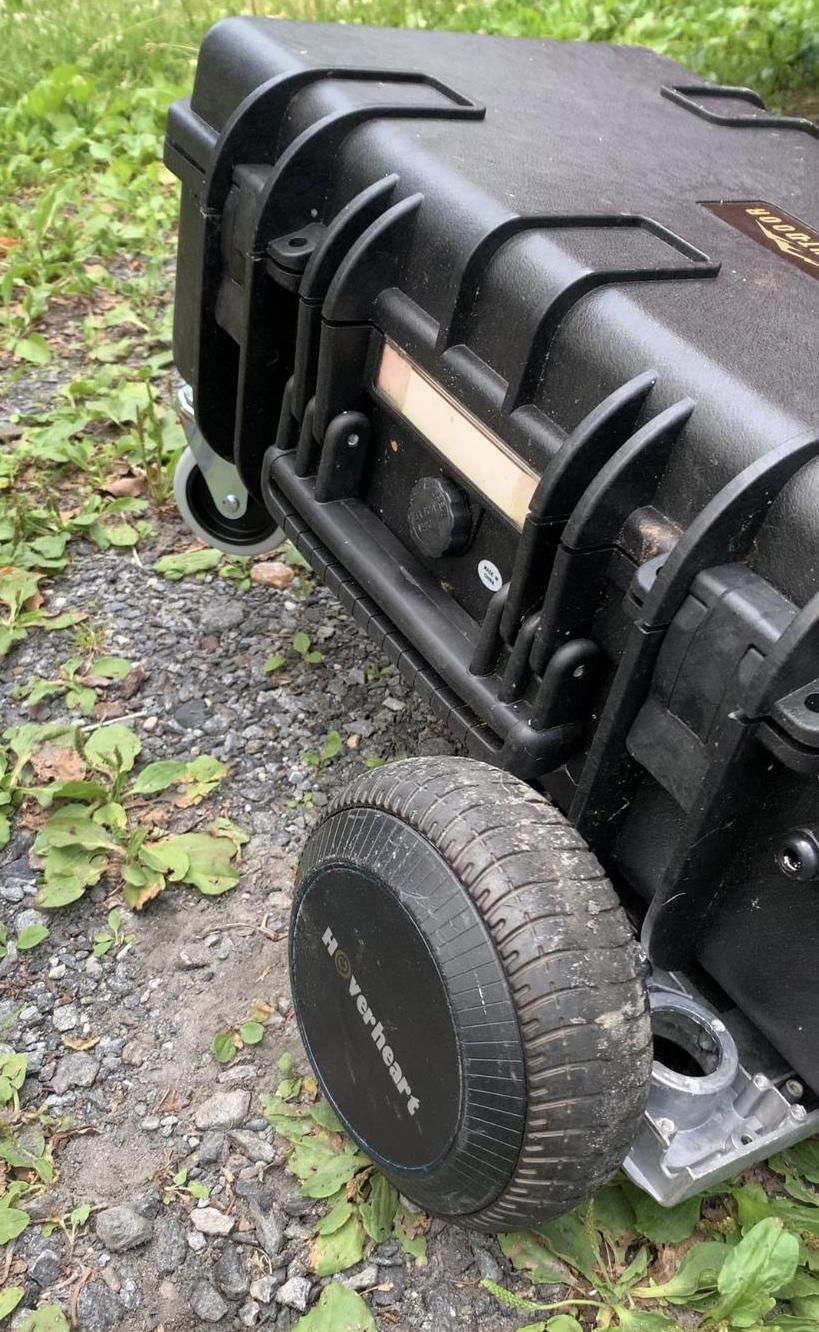
Overall Boxbot design
The success of this project was based on two key factors:
- Hoverboard hub motors are sealed and waterproof, can carry a good payload, are capable of navigating outdoor terrain like gravel and grass, and are somewhat readily available.
- Pelican-style plastic boxes are not only able to protect your electronics against the elements, but are also sturdy enough for hub motors to be directly bolted on, and able to carry additional payload on top.
Regardless of what future tasks you might have in mind for your outdoor robotic base, these parts are required for this design. Other advantages of using a case of this type is that you can easily open and close it to make adjustments, and you can conveniently carry the entire robot with the case’s handle.
Parts list for your Boxbot
Some of the equipment listed here is optional. For example, you might not need a night-vision camera if you won’t operate it at night and you will not need a solar panel and charge controller if you plan on using your rover occasionally and charging it in-between.
- 1 x Weatherproof plastic case ($30.50): This is the key to protecting your electronics and holding the robot together. Make sure it is a thick, strong plastic and can fit the solar panel mounted on top. Finally, get one with adjustable foam inside - this is very handy for cushioning your electronic components.
- 1 x Night vision camera ($40): Night vision is optional, but a webcam of some sort is highly recommended.
- 1 x Raspberry Pi 3B or 4B or 5 with microSD card ($100): Note: Due to supply shortages, Raspberry Pi prices are fluctuating dramatically.
- 1 x 12V Battery ($65): Lots of options here - some motors might run better on 24V. You can use a battery with less storage if you don’t plan to run it continuously.
- 2 x Brushless hub motor wheels (2 x $30 = $60): Better yet - source them from a used hoverboard (this is what I did, sorry son).
- 1 x USB Gmouse GPS module ($20): optional
- 1 x Solar charge controller ($20): optional
- 1 x 25w Solar panel ($10): optional
- 1 x 12V to 5V DC USB Type-C Right Angle Step-Down Power Converter ($13.50): To power the Pi from a 12V battery.
- 2 x Brushless motor controller (2x $18 = $36)
- 2 x Caster wheel (2x $5 = $10)
- 1 x Galvanized nuts/bolts, water sealing epoxy or caulk, washers, misc wires, brackets, etc ($15): Bolts are for mounting your hub motors and other components. I used a bracket I had lying in my basement plus some brackets/rails from my kids’ erector set to mount the solar panel.
You’ll also need some basic tools:
- Screwdrivers
- Drill
- Drill bits
- Socket or combination wrenches
- Hack saw
- Soldering iron and solder
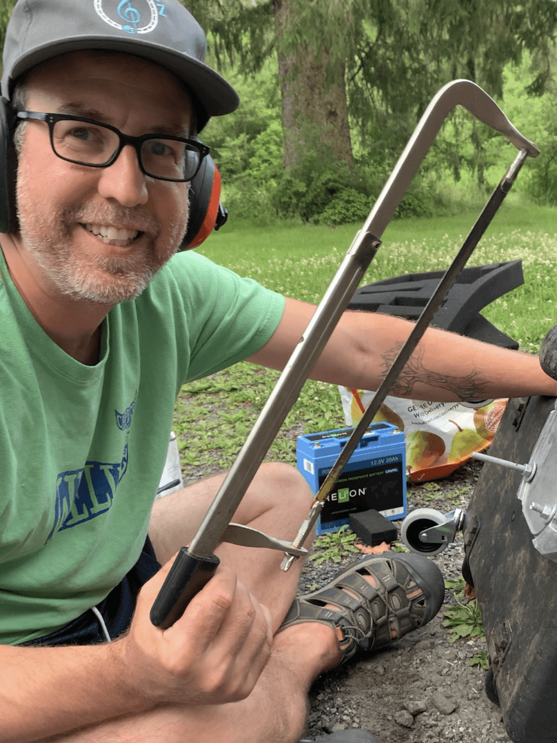
Build the base of your Boxbot

Hoverboard motors that come out of a toy hoverboard usually have large metal mounting brackets attached to them. This makes it much easier for you to attach them to the plastic case, and distributes the torque of the motors across more of the plastic case bottom, making the design more durable. However, I faced a problem that likely you will face as well: the brackets won't mount flat and flush against the bottom of the case unless you cut part of them off that is rounded. For this, I used a hacksaw. Hard work, but someone's gotta do it.

Next, you’ll mount the caster wheels to the “front” of the box (meaning what will be the front of the robot, which in reality is the left or right side of the box when facing the side of the box with the handle), and the hub motors to the rear, trying to ensure that the hub motor wheels are parallel to each other, and are not too close to the sides of the case. The caster wheels I bought had bolts attached, so I simply drilled holes through the bottom of the case, pushed them through, added washers and tightened the nuts securely.
For the hub motor mounts, drill two holes through each mount, line each one up, then drill through these holes into the bottom of the plastic case. While doing this I realized that I’d also want to run the wires from the hub motor into the case under the mount (to better protect the wires), so I drilled a smaller hole under where each of the mounts would be for that purpose.

At this point, I want to mention that although the case is intrinsically waterproof, we’ll want to make sure that we waterproof any holes that we make in the case. For this, I used marine epoxy from the hardware store, surrounding where the bolts went through the case. You can do the same where you pass the wires into the case; for added strength you can also use wire pass-throughs.
To attach the hub motors, use galvanized carriage bolts with washers inserted from the inside of the case out to the bottom, then put the bolts through the mounts, add washers and nuts and tighten securely. The bolts I had were way too long, so I had to remove the excess length with the hacksaw - you can avoid this by getting the correct length from the beginning - just measure the depth of the mount plus the case thickness, plus some excess for the washer and securing the nut!
At this point, you should have a not-yet-powered but assembled wheeled base!
Try pushing your base around, but don't be too sad if it doesn't go perfectly straight; caster wheels don't exactly lend themselves to that (especially when not faced with constant forward force; you know this if you've ever let go of your shopping cart in the grocery store in the middle of a push).
If you’re feeling brave, try sitting on it (carefully!) to see if it can support your weight. This will depend wildly on your weight and the strength of the case you purchased; if you are worried you could try putting something else less heavy on top like a couple cinder blocks or barbells.
Now could be a good time to attach a camera in a similar way to how you attached the wheels, but through the top of the case. Don’t forget that wherever you decide to feed the camera wire into the case, you’ll want to be sure you leave enough slack to open and close the case. I found that the rover handles much better with the hub motors in the back, acting as rear-wheel drive. If you are not sure if that’s how you’ll want to run yours, wait until after you’ve tested how it handles, and then mount a camera.
Wire it up
OK, I’ll be honest. I wanted to add an exclamation point here to motivate us - because in reality, this is the hardest part of the project. Specifically, setting up the motor controllers correctly is a bit of a challenge but I will do my best to describe how to best navigate them here.
Brushless motor controllers
Be sure to buy motor controllers that are built specifically for brushless motors. This is imperative because brushless DC motors (BLDC for short) have a tradeoff: while they and their controllers are more expensive and complicated to set up, they are more reliable and durable. Brushless motors do not rely on mechanical brushes that are prone to wear; instead they require an electronic communicator in the form of a more expensive and complex motor controller.
Let’s get to it. Note that all of the steps in this section will need to be done twice, as we will be controlling two motors (one on each side of the base). The procedure for each side will look like:
- Solder motor controller
- Wire the hub motor to the motor controller
- Wire the battery to the motor controller
- Test controlling the motor with the motor controller potentiometer
- Wire to the Raspberry Pi
With the brushless motor controllers I used, you’ll have to first solder a jumper where indicated in this diagram (label starts with “normally disconnected”). This allows the pi to control the motor with PWM. You’ll also need to solder two pins to the controller just to the left of the white wire harness mount. (P.S. - A truly clutch solder tip for those of you who may not be very experienced with soldering: heat the pin with the soldering iron, not the solder itself! Once the pin is hot, touch the solder to it. When someone taught me this it changed my life.)
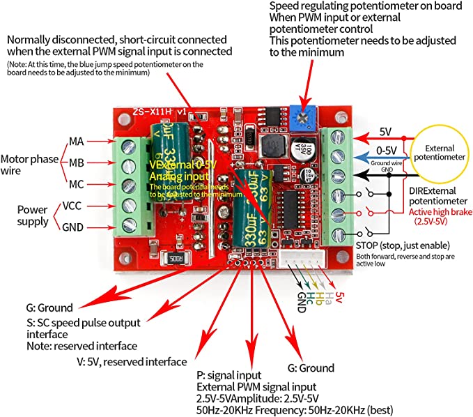
You’ll then connect the motor phase A, B, and C wires from your hub motor to the left side of the controller, and the 5 hall sensor wires to the white wire harness on the bottom right. It is also worth mentioning that you may need to extend the wires from your hub motors if they are not long enough to work with. Likely, the color of the wires from your hub motor will match the diagram - at the very least the 5V and GND should. If any of the phase wire colors don’t match, you might need to swap them when testing with the potentiometer.
Next, add wires to the VCC and ground terminals below the motor phase wires - this will supply power to your motor. You might find it easiest to use battery clamps to attach these wires to your battery.
CAUTION:
Be sure your base is on its side or otherwise supported so the wheels are free-spinning before attaching the battery!
Otherwise you might have a half-built rover flying and crashing off of your desk/workspace - this could be bad.
If everything is now wired up and lifted, attaching the battery and turning the potentiometer with a screwdriver should power the motor and the wheel should spin. When you’re done having fun with that, crank it back down until the motor is fully deactivated.
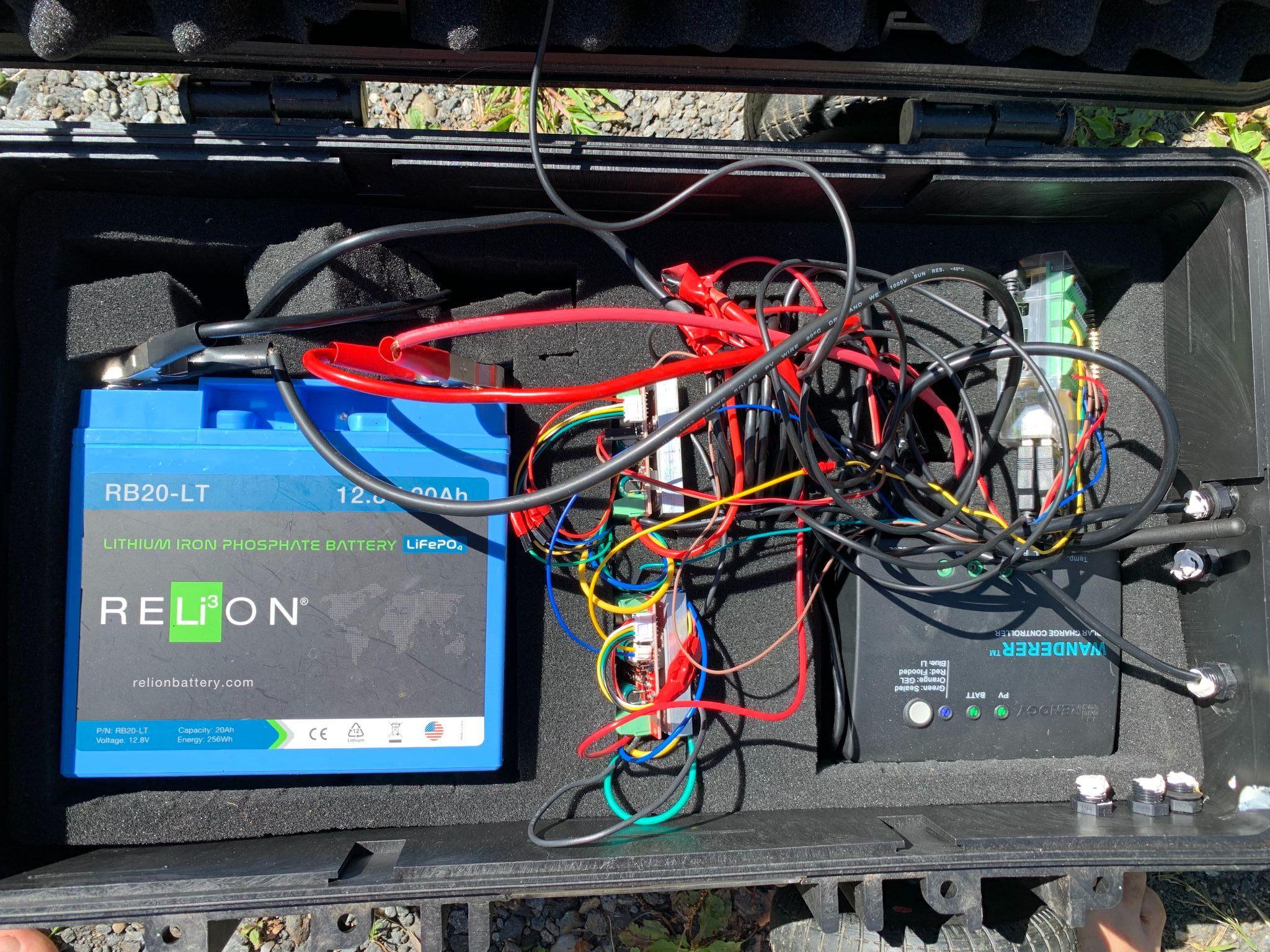
Organize the wires and components
Now might be the time to figure out where you’re laying everything out inside your case. You’ll need a space for:
- Your already wired motor controllers
- Your battery
- Your Pi
- Your solar charge controller, if you’re going to use solar charging
As mentioned, having a case that comes with foam that can be easily cut/shaped is very helpful. Make a cutout for each of your components, considering how you are going to run your wires. You don’t need to match my layout pictured here, in fact it could certainly be better organized.
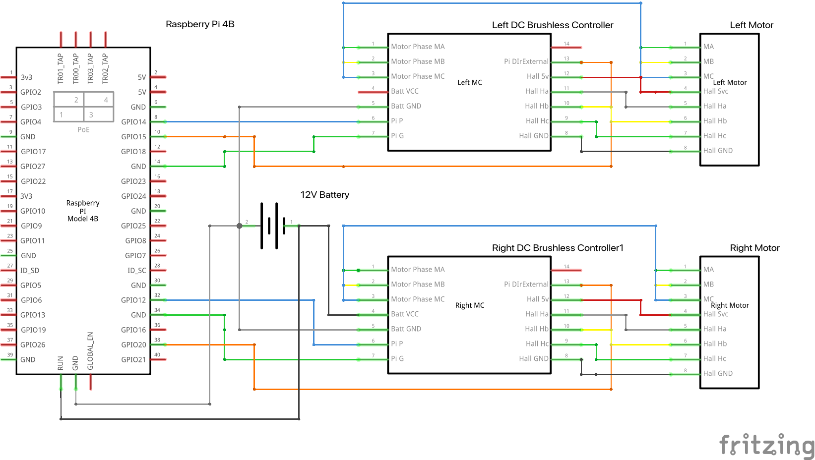
Connect the motor controllers to the Pi
Once that’s sorted out, we’re ready to connect 3 wires from the motor controller to the Pi (you’ll probably need a Pi pinout diagram handy):
- One from the pin you added labeled G to any GND terminal on the Pi
- One from the pin you added labeled P to any available GPIO pin on the Pi
- One from terminal labeled DIRExternal potentiometer to any available GPIO pin on the Pi
Finally, you’ll want to connect the wires from the 12V to the 5V Pi power converter to the battery.
At this point, you can plug in any extra components to the Pi (GPS and camera, if you are using them). If they are USB-based (like ones in the parts list), this is straightforward.
Bring your robot to life
Viam config overview
We’ve now got all the hardware and wiring set up, so it is time to configure your robot to be controlled with software. You might be bracing yourself, as this part is usually much harder than what you just did. However, the Viam platform makes it relatively painless.
First, let’s install viam-server on your Pi. It should only take a few minutes and once you’re done, you are ready to configure your robot.
The Viam platform represents both individual hardware pieces and logical groupings of hardware as components. Higher-level control is surfaced with services. For this project, we’ll configure:
- One board component representing our Raspberry Pi
- Two motor components
- One base component, referencing the two motors that make up the base
Configuring these components will allow you to control your rover through the internet both manually and programmatically. Later, we can do more interesting things by configuring:
- A camera component (optional but recommended)
- A movement sensor component, which in this case represents GPS (optional)
- A vision service, which allows us to use machine learning models to detect various things in the robot environment
Setting up our Boxbot config using the Viam app
Board component
Navigate to the CONFIGURE tab of your machine’s page in the Viam app. Click the + icon next to your machine part in the left-hand menu and select Component. Select the board type, then select the pi model. Enter a name for your board and click Create. You can name it whatever you want, but you’ll reference this name later. We’ll call it “local” in this example.
Motor component
Next, create another component of type “motor”, model “gpio”. Call it “left” to represent the motor on the left side of your rover. Now we’ll need to add some attributes. We’ll need to reference the board component we created in the last step by name, and the GPIO pins we connected from this motor to our Pi. Other attributes (Max RPM, PWM Freq) are important for motor control (Note that these might vary based on your specific hub motors, check the data sheet if you have one; or you can try the ones we use in this tutorial). Once you’ve configured the “left” motor, repeat for the “right” - make sure you’re mapping the correct GPIO pins for each. Finally, one of the two motors we are connecting will need the “Direction Flip” attribute set to “true”. It’s ok if you are not sure which one, you can always switch them later after testing.
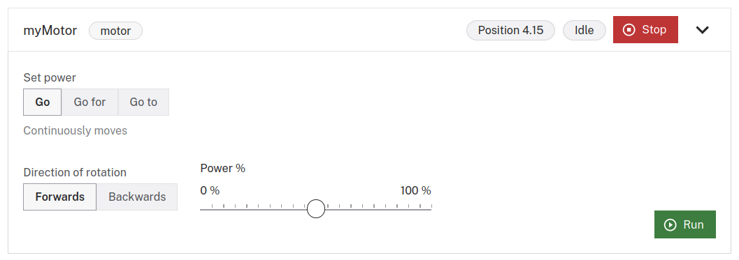
At this point, you can try controlling your motors with the Viam App. Navigate to the CONTROL tab. If all is set up correctly, you’ll see cards for your left and right motors on this page. Open one up, and if your rover is in a safe position (on the ground or propped up), try running one!
CAUTION
Be aware that these are powerful motors, so you don’t want to start at 100% power right away.
If the motors don’t appear on the control page, or are not running when expected, first check the Logs tab to see if you see any errors - which would likely point out a bad configuration (a typo, a misplaced or missing attribute, etc). If not, double check your wiring and how it maps to the GPIO pins you’ve configured.
Base component
Now, let’s configure a “base” component that references both of our motors. This will allow us to control our robot’s movement through a single interface. Add a new component of type “base”, model “wheeled” - which represents a wheeled base with two powered wheels. The “left” and “right” attributes reference the motors you’ve configured by name. You can measure your wheel’s circumference and width between wheels, which will allow the Viam platform to properly calculate how to steer your base.
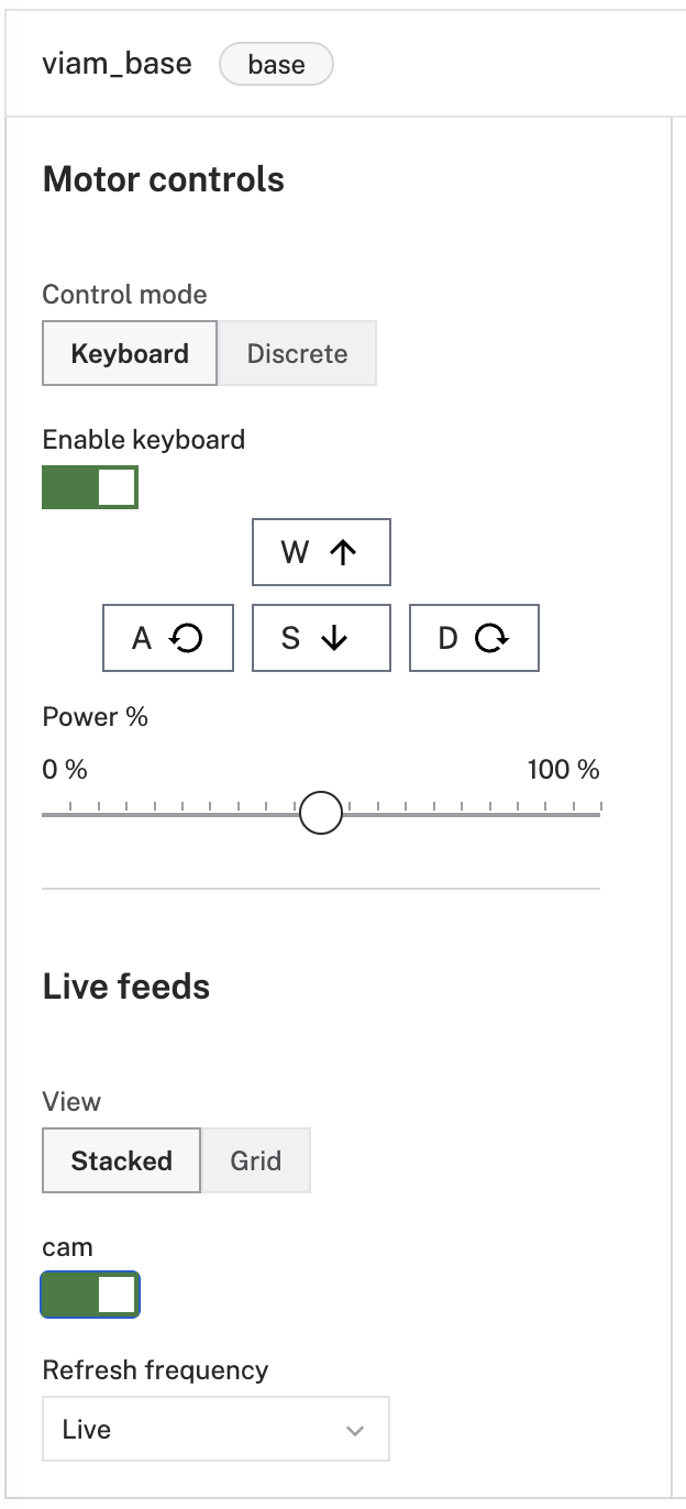
Take your Boxbot for a drive

You can now have some real fun. Try driving your rover by keyboard. Drive your robot programmatically, use a color detector or a machine learning object detector to interact with the environment. Check out our Python SDK documentation (or another SDK in the language of your choice) and start planning how you’ll use your sturdy outdoor rover to do real things! Or, expand what your outdoor rover can do by adding a camera, movement sensor, or other component.
I had a lot of fun building this rover, and hope you did as well. I am now programming mine to help keep unwanted animals away from my garden, garbage, and egg-laying ducks using Viam’s data management, vision, and navigation services. We are interested in hearing what you plan on doing with yours. You can tell us all about it over in the Viam Community Discord.